Visualizzazione post con etichetta BJT. Mostra tutti i post

lunedì 3 dicembre 2012

Using a darlington pair to boost your driver

As seen in this post about creating a BJT driver to control a load with a microcontroller output, there is some scenarion in which the required load current does not allow to use a simple transistor to do the job. This is due to the fact that cheap BJT for high current have usually a low DC gain.
Fortunately if you have a cheap power transistor and a cheap switch transistor you can create a configuration to boost the DC gain: The Darlington Pair.


With this configuration the gain is the product of the two gains:


We can easily simulate the circuit to create the classical Vce/Ic chart with various basis currents. In the example chart I did the lowest basis current is 0.1mA while the bigger one is 1mA. Let see the chart below:

As we can see when the basis current is 1mA, the Ic current is 3.6 A, so the current gain is about 3600 !. The drawback we can see from the chart is the Vcesat being a little higher than in a simple transistor ( this means more power the transistor should bear ) and, even if not visible from the chart, the Vbe(on) is almost twice than a regular chart. If you can deal with this limitation, and usually we can, this is probably one of the cheapest solution to drive a power load with a small current digital output.

Why do we need a diode in reverse parallel to a relay?

When we drive a relay with a transistor we always see a diode in reverse parallel with it. Is just a precaution, some sort of ritual, can we remove it? The answer is NO, we can't remove it, it is not ritual, and avoiding to use it is a dangerous ( at least for the driver ) error.
Lets use the same circuit we see when we talk about saturation, but just put a coil instead of a resistive load. Even if there is no more the resistor, I put a series resistor of 46 Ohm in the coil parameters. The 46 mH inductance is not a random value, but a reasonable value for a mini relay for PCB.
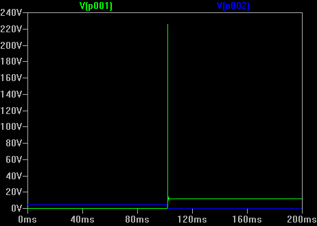
As we can see there is not the required diode. What we could expect? The interesting part happens when the transistor switch off. When the transistor is on, into the coil there is a certain amount of energy as a magnetic field. By breaking the current such energy should dissipate somewhere, and this would happen as a current flowing into the coil itself and the parasitic capacitance of the circuit. Lets try to simulate the circuit to see how this happens:
The green line is the voltage on the BJT collector. Amazing! the voltage goes to more than 200V! Even if the highest voltage on the whole circuit is just 12 V ! So can you imagine what's happn to the poor BJT after some switches? It will probably die ungloriously :(
Let's try to add the always present diode:
We expect the energy now dissipate on the coil resistence trought the diode, so we have this result in simulation:
Now the blue line is the voltage on the transistor collector. There is still a little spike, but it is at most 13V, a voltage the BJT can easily play with, and now the circuit is safe.


So I really hope I managed to show why the opposite parallel diode is needed, in an easy to understand way.

How to use a BJT as a switch

This is a typical application of a BJT, really useful if you want to drive a load from a digital output of a microcontroller, when the current of that output is not enought. Here we study how to design the circuit. Have a look at the typical circuit:
The RLoad is the load we want to drive. Pulse emulates a digital output, it is a square wawe generator we will use next in the analysis to show the circuit at work. We need to calculate the R1 value in order to properly drive the load, so how can we do it ?
We first need to ensure the transistor works in saturation zone: this is the starting point; by working in the saturating zone the BJT works (almost) as a switch, and this is what we need.
Lets say the constraints we need for the design:

  1. BJT must work in saturation mode
  2. BJT must handle the required power.
  3. Digital Output current must be lower than the maximum accepted
  4. Of course, load must be driven with the proper voltage.
A trick to saturate the transistor is to ensure that:
In simple words, ensure that the basis current is a lot greather than the one required to drive the load in linear mode. Here Hfe is the DC gain. Since we need to be safe, consider the minimum Hfe from the datasheet of the used bjt, in this case it is 100. We calculate the current flowing in the load by simply:


Since our Hfe is 100, the basis current required is >> 2.45 mA.
Many digital output for microcontroller drive a current of 20mA, so we can decide to bias the BJT wit a current of 12mA, enought to saturate, but not too mutch for the micro controller. 
With this value we can design resistor R1:


We round this value to 330ohm.
Now we can simulatethe circuit ( I'm using LTSpice ) to see if we are right. Let'see the Vout, and ILoad chart:


As ve can see the red line ( the current flowing in the load ) goes o the expected current when the digital output goes high.
Let'see what happen to the voltage around the BJT, this with the current let us calculated the power:

As we can see, when the current flow inside the BJT, the voltage is around 0.3 V so let's calculated the needed BJT power:


This is really far away from the maximum BJT power, that is from the datasheet 625 mW, so our circuit can safely operate.

So, what we left apart:


  • We did not put a diode in parallel to the load, Why?
    • Because the diode is needed for an inductive load, so put it always you have such a load ( a relay for example ) I would like to show WHY is needed in another post
  • What if the Hfe is not enought so we can't saturate the transistor ? 
    • You must choose another, or use a darlington pair, I would like to show it too in another post.